Difference between revisions of "Nanoscale Ultrasonic Transducers"
(→Plate Transducers) |
|||
| (30 intermediate revisions by the same user not shown) | |||
| Line 1: | Line 1: | ||
| + | __NOTOC__ | ||
| + | ==Nanoscale Ultrasonic Transducers== | ||
[[Image:BNC_example_transducers.png| thumb | 300px|alt=alt text|two approaches to making nanoscale transducers]] | [[Image:BNC_example_transducers.png| thumb | 300px|alt=alt text|two approaches to making nanoscale transducers]] | ||
| − | |||
| − | + | Ultrasound is a powerful tool for diagnosing medical and mechanical problems. Conventional ultrasonics work at megahertz frequencies and with wavelengths of 1-2mms to 10’s mm. This means it cannot "see" very small objects at the nanoscale. Our new transducers are so small it is impractical to communicate with them electrically. Instead we have devised a non contact method of talking to them using short pulses of laser light. | |
| − | + | ||
| − | + | ||
| + | We have adopted two approaches for producing these transducers, one method builds plates devices the other uses self assembled nanoparticles. The transducers are made from alternating metal and soft transparent layers. They have optical and mechanical resonances and so the devices have to be made such that they work well both mechanically and optically | ||
| + | |||
| + | <br style="clear:both" /> | ||
| + | ==Plate Transducers== | ||
| + | {|align="right" | ||
| + | |[[file:Model_ito.png |thumb|150px|alt=alt text|model of mechanical motion]] | ||
| + | |[[file:BNC_opticalmodel.PNG |thumb|150px|alt=alt text| optical model]] | ||
| + | |} | ||
| + | |||
| + | The transducer is made up of alternating layers of gold and ITO to produce a sandwich structure of the reflective metal layers and the soft transparent core. | ||
| + | |||
| + | We have modeled the optical behaviour of these devices as the gold and ITO layer thicknesses are altered . The model shows that the devices have a wide operating region where there is good sensitivity.With the optimal device being made from 40 nm gold layers sandwiching a 160nm ITO layer. | ||
| + | |||
| + | We have also constructed an FE Mechanical model of the devices to show how the devices behaviour when they are excited by an optical pulse. the model shows the difference in displacement between the the two gold layers, this motion has a main frequency component of ~9GHz with harmonics up to ~70GHz | ||
| + | |||
| + | <br style="clear:both" /> | ||
| + | |||
| + | {|align="right" | ||
| + | |[[file:BNC_ASOPS_Layout.jpg |thumb|150px|alt=alt text|Experiment system]] | ||
| + | |[[file:BNC_5u_on_glass.PNG |thumb|150px|alt=alt text|240nm x 5 micron transducers on substrate]] | ||
| + | |} | ||
| + | |||
| + | These devices can be made using standard photolithography techniques where an array of transducers is made on a glass substrate by exposing photo resist to UV through an optical mask. once developed the gold and ITO layers are sputter coated and lift off reveals the structures on the substrate. This approach is very useful as we have an ordered array of devices which we can test in situ. Once tested we can release the transducers from substrate into solution and then reattached them for measurements. | ||
| + | |||
| + | These transducers are 240nm high with 5-25 micron patch sizes. The lateral dimensions as limited by our in house photo lithography equipment. Other techniques could be employed to reduce the lateral dimensions further. | ||
| + | We test the devices with a picosecond laser ultrasound system, which utilises locked femtosecond lasers with control electronics to provide the pulse delay ([[ASOPs Laser]]). | ||
| + | The blue pump pulse is absorbed by the transducer and set it in motion. The probe pulse then measures the interaction of device with the generated acoustic waves. | ||
| + | |||
| + | <br style="clear:both" /> | ||
| + | |||
| + | {|align="right" | ||
| + | |[[file:BNC_ito_poly_patch.jpg |thumb|150px|alt=alt text|Experimental result]] | ||
| + | |[[file:BNC_hair2highlightred.PNG |thumb|150px|alt=alt text|Transducer Attached to hair]] | ||
| + | |} | ||
| + | |||
| + | We have measured the response on a 240nm x10 micron patch and they agree very well with modelled response. The main frequency is around 9 GHz and there are harmonics up to ~70GHz. The weighting of harmonics do differ from those in the model, this could be due to slight variations in actual material properties and final created layer sizes being different from those modelled. | ||
| + | |||
| + | We hope to employ different dicing techniques in the future to reduce the lateral size of the transducers to below 1 micron. | ||
| + | |||
| + | <br style="clear:both" /> | ||
| + | |||
| + | ==Nanoparticle Transducers== | ||
| + | {|align="right" | ||
| + | |[[file: spheremodel.png |thumb|150px|alt=alt text|model of mechanical motion]] | ||
| + | |[[file: Nps_optical_model.PNG |thumb|150px|alt=alt text| optical model]] | ||
| + | |} | ||
| + | |||
| + | The transducers are made with a similar structure to the plate devices. There is a soft transparent core made from silica nanoparticle. This core is then coated with small gold nanoparticles to form a shell. | ||
| + | |||
| + | The optical response of the transducers has been investigated via Mie theory. The transducers have repeating regions of high sensitivity with changes in the layer thicknesses we need to make sure the particles we make are within one of these high sensitivity zones. | ||
| + | |||
| + | We have 3D FEM mechanical models that show the mechanical motions of these devices once exciting with a laser pulse. We see from the model that these transducers have one dominant mode,a breathing mode,and there are other higher order harmonics although they are much smaller than in the plate case. | ||
| + | |||
| + | <br style="clear:both" /> | ||
| + | [[file:BNC_paper-nps.PNG |right|thumb|300px|]] | ||
| + | To fabricate the transducer we firstly make gold nanoparticles of the chosen shell size (10nm). The silica cores are made to size and functionalised with amine groups. Mixing the particles together creates the final transducers as the gold particles bind to the functional groups with electrostatic attraction forming a gold shell. | ||
| + | |||
| + | Depending on the recipe and process followed it is possible to control the size of the produced particles. We have made transducers with 180nm cores and 10nm shells and have imaged the transducers to look at the coverages of the shells. | ||
| + | |||
| + | The main advantage of this approach is the quantity of transducers made in each batch typically trillions, making this a viable approach for mass producing devices. We need to improve the fabrication process to control the particle size variance to keep the transducers in the optimal operating region | ||
| + | |||
| + | Testing of these devices is on going. | ||
| + | |||
| + | <br style="clear:both" /> | ||
| + | |||
| + | ==Related Publications== | ||
| + | <bibtex> | ||
| + | @article{smith_design_2011, title = {Design and fabrication of ultrasonic transducers with nanoscale dimensions}, volume = {278}, issn = {1742-6596}, url = {http://iopscience.iop.org/1742-6596/278/1/012035}, doi = {10.1088/1742-6596/278/1/012035}, journal = {Journal of Physics: Conference Series}, author = {R Smith and A Arca and X Chen and L Marques and M Clark and J Aylott and M Somekh}, year = {2011}, pages = {012035}, pdf ={http://optics.eee.nottingham.ac.uk/w/images/7/79/Paper_2010_JoPCS_LU2010_NanoscaleTransducers_RJS.pdf}}</bibtex> | ||
| + | <bibtex> | ||
| + | @techreport{noref, | ||
| + | title = {Set for Britain 2011 London}, | ||
| + | author = {Richard Smith}, | ||
| + | year = {2011}, | ||
| + | institution = {The University of Nottingham}, | ||
| + | type = {Poster}, | ||
| + | pdf = {http://optics.eee.nottingham.ac.uk/w/images/9/99/Poster_2011_SfB_Westminster_Nano_Transducers_RJS.pdf} | ||
| + | } | ||
| + | </bibtex> | ||
| + | <bibtex> | ||
| + | @techreport{noref, | ||
| + | title = {AFPAC 2011 Frejus}, | ||
| + | author = {Richard Smith}, | ||
| + | year = {2011}, | ||
| + | institution = {The University of Nottingham}, | ||
| + | type = {Talk}, | ||
| + | pdf = {http://optics.eee.nottingham.ac.uk/w/images/e/e6/Talk_2011_AFPAC_RJS_nano_transducers.pdf} | ||
| + | } | ||
| + | </bibtex> | ||
| + | <bibtex> | ||
| + | @techreport{noref, | ||
| + | title = {LU2010 2010 Bordeaux}, | ||
| + | author = {Richard Smith}, | ||
| + | year = {2010}, | ||
| + | institution = {The University of Nottingham}, | ||
| + | type = {Talk}, | ||
| + | pdf = {http://optics.eee.nottingham.ac.uk/w/images/c/c4/Talk_2010_LU2010_Bordaeux_RJS_nano_transducers.pdf} | ||
| + | } | ||
Latest revision as of 14:08, 20 April 2011
Nanoscale Ultrasonic Transducers
Ultrasound is a powerful tool for diagnosing medical and mechanical problems. Conventional ultrasonics work at megahertz frequencies and with wavelengths of 1-2mms to 10’s mm. This means it cannot "see" very small objects at the nanoscale. Our new transducers are so small it is impractical to communicate with them electrically. Instead we have devised a non contact method of talking to them using short pulses of laser light.
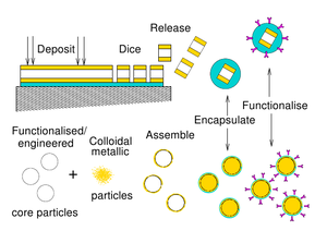
We have adopted two approaches for producing these transducers, one method builds plates devices the other uses self assembled nanoparticles. The transducers are made from alternating metal and soft transparent layers. They have optical and mechanical resonances and so the devices have to be made such that they work well both mechanically and optically
Plate Transducers
The transducer is made up of alternating layers of gold and ITO to produce a sandwich structure of the reflective metal layers and the soft transparent core.
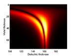
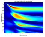
We have modeled the optical behaviour of these devices as the gold and ITO layer thicknesses are altered . The model shows that the devices have a wide operating region where there is good sensitivity.With the optimal device being made from 40 nm gold layers sandwiching a 160nm ITO layer.
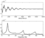
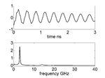
We have also constructed an FE Mechanical model of the devices to show how the devices behaviour when they are excited by an optical pulse. the model shows the difference in displacement between the the two gold layers, this motion has a main frequency component of ~9GHz with harmonics up to ~70GHz
These devices can be made using standard photolithography techniques where an array of transducers is made on a glass substrate by exposing photo resist to UV through an optical mask. once developed the gold and ITO layers are sputter coated and lift off reveals the structures on the substrate. This approach is very useful as we have an ordered array of devices which we can test in situ. Once tested we can release the transducers from substrate into solution and then reattached them for measurements.
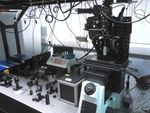
These transducers are 240nm high with 5-25 micron patch sizes. The lateral dimensions as limited by our in house photo lithography equipment. Other techniques could be employed to reduce the lateral dimensions further. We test the devices with a picosecond laser ultrasound system, which utilises locked femtosecond lasers with control electronics to provide the pulse delay (ASOPs Laser). The blue pump pulse is absorbed by the transducer and set it in motion. The probe pulse then measures the interaction of device with the generated acoustic waves.
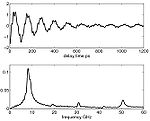
We have measured the response on a 240nm x10 micron patch and they agree very well with modelled response. The main frequency is around 9 GHz and there are harmonics up to ~70GHz. The weighting of harmonics do differ from those in the model, this could be due to slight variations in actual material properties and final created layer sizes being different from those modelled.
We hope to employ different dicing techniques in the future to reduce the lateral size of the transducers to below 1 micron.
Nanoparticle Transducers
The transducers are made with a similar structure to the plate devices. There is a soft transparent core made from silica nanoparticle. This core is then coated with small gold nanoparticles to form a shell.
The optical response of the transducers has been investigated via Mie theory. The transducers have repeating regions of high sensitivity with changes in the layer thicknesses we need to make sure the particles we make are within one of these high sensitivity zones.
We have 3D FEM mechanical models that show the mechanical motions of these devices once exciting with a laser pulse. We see from the model that these transducers have one dominant mode,a breathing mode,and there are other higher order harmonics although they are much smaller than in the plate case.
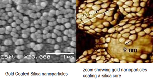
To fabricate the transducer we firstly make gold nanoparticles of the chosen shell size (10nm). The silica cores are made to size and functionalised with amine groups. Mixing the particles together creates the final transducers as the gold particles bind to the functional groups with electrostatic attraction forming a gold shell.
Depending on the recipe and process followed it is possible to control the size of the produced particles. We have made transducers with 180nm cores and 10nm shells and have imaged the transducers to look at the coverages of the shells.
The main advantage of this approach is the quantity of transducers made in each batch typically trillions, making this a viable approach for mass producing devices. We need to improve the fabrication process to control the particle size variance to keep the transducers in the optimal operating region
Testing of these devices is on going.
Related Publications
R Smith, A Arca, X Chen, L Marques, M Clark, J Aylott, M Somekh - Design and fabrication of ultrasonic transducers with nanoscale dimensions
- Journal of Physics: Conference Series 278:012035,2011
- http://iopscience.iop.org/1742-6596/278/1/012035
Bibtex<div>Author : R Smith, A Arca, X Chen, L Marques, M Clark, J Aylott, M Somekh
Title : Design and fabrication of ultrasonic transducers with nanoscale dimensions
In : Journal of Physics: Conference Series -
Address :
Date : 2011
</div>
Richard Smith - Set for Britain 2011 London
- Technical Report - Poster, The University of Nottingham ,2011
- BibtexAuthor : Richard Smith
Title : Set for Britain 2011 London
In : Technical Report - Poster, The University of Nottingham -
Address :
Date : 2011
Richard Smith - AFPAC 2011 Frejus
- Technical Report - Talk, The University of Nottingham ,2011
- BibtexAuthor : Richard Smith
Title : AFPAC 2011 Frejus
In : Technical Report - Talk, The University of Nottingham -
Address :
Date : 2011
<bibtex> @techreport{noref, title = {LU2010 2010 Bordeaux}, author = {Richard Smith}, year = {2010}, institution = {The University of Nottingham}, type = {Talk}, pdf = {http://optics.eee.nottingham.ac.uk/w/images/c/c4/Talk_2010_LU2010_Bordaeux_RJS_nano_transducers.pdf} }
